Posts

Showing posts from 2017

forgery

Image
 Ronny and Matt from Church invited some youth to try simple forging.  Ronny brought an anvil and some know-how.  Matt brought a little propane forge. Starting from some simple rod stock, a couple guys each got to pound on the red hot metal: to make a stylish little letter-opener:  I got to hammer too, and made a wee "garlic cleaver": I didn't do much of the metal - i just supplied some dumb hammering while Ronny moved the work - but I was proud of the handle: I cut off 5" of an oak branch that had fallen during the recent storm, shaped it with a rasp, then burned it with a blowtorch to get the color.  I sealed it with a quick clear coat spray.  The handle only took about 90 minutes (mostly the rasp), and I was pleased with the comfort and color. I mounted it on the blade by drilling a hole in the wood (slightly undersized for the tang), heating up the metal to really hot, and shoving them together.  The hot metal burned its shape into the woo

stained glass triakis icosahedron

Image
It was hand-made from cut glass (score and snap), bound in copper foil (rather than lead came), and soldered with 60/40 (tin/lead) solder.The lighting is provided by strip of LED lights - it consumes little power, and could be supplied by a wall adapter or computer’s USB port.I find the shape to be both aesthetically and mathematically pleasing. On the Making First make a a lot of uniform isosceles triangles (at least 60, probably more if any turn out badly).  I made mine about 2.5 inches tall and 1.5 inches wide (a very poor-man's golden ratio). Bind all their edges in copper foil tape, solder the borders Solder them all together so internal dihedral angles are all exactly 138.189685° I made a little jig out of coat hangers and hot glue to help get the angles right. Before closing it up, shove an LED light strip in there. coat hanger jig calibrated to exactly 138.189685° On the Triakis Icosahedron The shape can be seen as a platonic icosahedron

Hearth finale... finally

Image
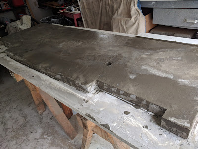
The top veneer of newer concrete never really hardened into a surface I could polish.  It remained weak and grainy, so I scraped it all back off: In removing the little PVC segment i'd used to cast a hole for the gas key, I chipped more of the surface.  Vexing! I gave it some sanding afterward, but because I'd given up on it looking "nice" I didn't go beyond 200 grit polishing (and I had pads going up to 3000!). I called friends to help me carry it (300+lbs) inside.  I had to cut a bunch of the wood to get it to fit right -- the standard approach of measure once, cut 5 times -- but it's in.  I didn't wind up gluing or shimming it at all -- it's pretty solid. This was a frustrating project, but the flaws aren't as offensive in person as I feared they would be.  They're less obtrusive than I'd feared, and all through christmas people were sitting on the hearth, so you couldn't see them anyway. The overall effect is fin

Hearth Update

Image
Follow-up to the recent follow-up: After casting the hearth and grinding out the flaws, and then leveling the depressions with cement slurry, I was unsatisfied with the resulting variation in color and texture: (I know i could make the polisher lines go away, but the major blotches weren't going to "buff out"). So my mother and I built a new form around the existing block: and poured (this time right-side-up) and troweled some new mortar (one batch for consistent color).  I tried really hard to get it reasonably smooth and pit-free, but tolerated some bumps (which i could later sand down).  It poured well, but unfortunately in my haste I tried to sand it again before it was sufficiently cured.  Worse, I did it in a highly visible area.  Because of the cold, two days was not enough (even with a space heater in the garage), to get it to sufficiently harden.  I mangled it pretty severely.  Very sad.  I think i'm done trying to make it perfect now -- we'

Robot Arm - sprockets and challenges

Image
Robot Arm Progress! Received and deployed the chain and sprockets: Now using a 3:1 reduction on the bottom of the arm (which bears the most strain), and use my 270 degree servo for that (giving me a 90 degree effective range, and converting my 20kg-cm to ~60kg/cm). using a 2:1 reduction on the middle of the arm. using 1:1 sprockets for the rotation. Chains and Sprockets!   Largest (48 tooth) gear at bottom of arm,  middle size (32 tooth) in the middle joint smaller (16T) on the servos (and on the underside to rotate the arm) Challenges I don't have a chain breaker, and that part was a lot harder than I imagined.  I pounded the pins out on my vise with a hammer and nailset, a nail, and a broken drill bit... just like the pros. I had trouble with a 3rd servo.  I traced through the various issues and determined it was particular to one of the "channels" I'd built to power the servos.  I tried a billion combinations of wires, and found that

little distractions

Image
A little light on project updates lately because: had a baby house lost power in a storm and i had to move out for a few days same storm threw large branches around the yard, crushing fences and breaking off my gutter and fascia. see: http://blog2.remingtons.org/2017/12/family-update.html for gutter and storm saga. So I have been: Dandling said baby Cooling heels and watching football at a friend's house for a while Replacing fascia, putting banged-up gutter back into place Chainsawing up fallen tree-matter. But even so I've made some progress - other updates to follow.

Follow-ups

Image
Concrete Hearth see:  http://projects.remingtons.org/2017/11/the-hearth-wants-what-it-wants.html After turning it out of its form, we (father-in-law and a friend and I) flipped the slab over.  The surface was nice and flat, but unfortunately had some surprisingly large air bubbles.  They weren't deep, so I tried grinding them out with a polisher borrowed from another friend.  I was able to reduce them, but it left little dimples which I didn't like.  So I did a skim coat of cement slurry (which is now curing, and can be seen below).  Hopefully i can take off the high spots of that without much trouble, because i was pretty generous. Duck Hut see:  http://projects.remingtons.org/2017/11/duck-hut.html The ducks stay up late partying most nights (til around 9pm -- the longer light keeps them laying even as the real days get shorter).  As you can see they're also ready for Christmas: Robot Arm see:  http://projects.remingtons.org/2017/11/mac-arduino-pi-perf

mac -> arduino -> pi -> perfboard -> regulators -> servos

Image
This is a continuation of the small electronics / microcontroller project mentioned earlier in http://evandaprojects.blogspot.com/2017/11/robot-claw-prototype.html http://evandaprojects.blogspot.com/2017/11/first-pi-project.html http://evandaprojects.blogspot.com/2017/11/pi-prj-1-update-1.html But I've shifted gears and instead of a gantry-like ASRS, I was thinking of trying to make a robot arm. Structure As usual, I will use a lot of what i have on-hand, and so instead of fancy aluminum t-channel structural members, I'll use 2x4s that I'll rip into thin slabs. I figured it'd need to rotate.  I didn't have any lazy susan bearings, so i stuck some casters on a board.  It could be smoother. Arms will get mounted to it using pieces of melamine (left over from the concrete casting)  and bolts (reclaimed from a bench swing that got crushed by a fallen tree). I made sprockets or gears - we'll see how i use them - with timing belt and plywoo

the hearth wants what it wants

Image
(see also  http://evandaprojects.blogspot.com/2017/11/fireplace-surround-rock-to-cedar.html ) The Plan: Initially I'd thought we'd buy a big slab of granite or stone and get it cut to shape for the hearth. The wife didn't see any she liked, or weren't cost-effective, and so suggested we try pouring a concrete one. Redesign: In building the form we decided to rethink the design for aesthetic reasons.  Instead of solid beams on the side going floor to ceiling, we decided the wood structure should sit on top of the hearth.  Unfortunately those sides are the main load-bearing elements of the whole thing, and now i need to cut them out. Approach: I figured if we poured the hearth, it could certainly support the wooden structure above, but I'd need something to hold it up temporarily while we cut out the supports and poured the concrete beneath it.  I removed some cedar and attached a 2x4 spanning the width, and held it up with jack stands on either side.  The

airboat

Image
I built an Airboat with normal RC components -- I'd never done anything with RC before. The chassis was made from the wooden pieces of my child's broken catapult model. The rear floats are 1L bottles, the front is another bottle (whose cap was lost, so covered with cling wrap). The electronics are a 7v NiMH battery powering a speed controller which in turn powers the RC receiver and the motor.  The receiver then controls and powers a servo. The servo controls a rudder (a pcmcia placeholder card!), the main motor turns a 10" propellor. Initially i wanted the fan at the back, but I wasn't sure how to make it high enough to avoid hitting the water but still not push the front end of the boat downward.  Eventually i put it on the front of the boat where it was much less of a problem. The entire thing is held together with tons and tons of hot glue. The good: I was really surprised at how well the rudder worked. the 7v battery never ran

pi prj 1 - update 1

Image
Spent another hour(ish) last night: Refining the old: screwed the motor to the 2x4 and put a belt on it and an idler pulley. connected the ends of the timing belt with masking tape and wrapped it with some stiff wire -- just like the pros. Something new:  Added a bump switch to the pi setup (which apparently requires a couple resistors too) Added some code to read the switch and reverse the belt. Put the code (99% of which is taken from the internet) on github . The idea is that eventually the bump switch will be activated by whatever carriage i have mounted on the belt, so the system will know the limit of the belt's range.  I'd need one on each side. Premium 2x4, professionally connected belt, and bump switch (middle-ish, on alligator clips) with some additional wiring (2 resistors and 2 jumpers) on the breadboard

first pi project

Image
Plan Pursuant to my aforementioned automated storage/retrieval project, I'd ordered a bunch of hardware.  I've played with Arduino before, and this time i wanted to try a raspberry pi. Equipment I ordered: * raspberry pi, model 3b -- $30 for a pretty full-featured computer! * a microSD card, since the pi needs it. * a pi " cobbler+ " (which lets me easily use the pi's pins on a breadboard and, more importantly, labels them) * a pack of 5 steppers, each with a small driver board (more on these later) * some timing belt and pulleys I had: * various power supplies, and a voltage converter/regulator * breadboard * wires and jumpers and alligators * a battery bank (because the pi needs more juice (2+ amps!) than any of my micro USBs supply) Setup An old ATX computer power supply supplies 12v to a buck converter/regulator that sends 7.3v to the motor driver. The battery bank supplies 5v at 2A to the pi, which (via the cobbler a

robot claw prototype

Image
I've been thinking about building a miniature single-aisle (2d) ASRS , like this: But simpler, and smaller.  Luckily, DIY CNC and 3d printing is fairly common now and I think i can use a lot of parts from those -- just tipped vertically. One tricky difference is that instead of a cutting or printing head, I'll need a little grabber claw and I want to minimize the wiring, weight, and complexity -- i was hoping to get away with just one motor rather than something to extend/retract an arm and another thing to pinch/release. That is: I want something that can reach out, grab something on a shelf, and pull back while holding it.  Then i want to be able to reverse it to put things on the shelf from the claw. There are a million awesome linkages in the world, but i find them very hard to think about. https://makezine.com/2015/04/20/understand-1700-mechanical-linkages-helpful-animations/ http://507movements.com/index02.html I guess the one i hit on accidentally was sort

fireplace surround - rock to cedar

Image
Plan : remove old rocks, replace with wood, hide some wires behind for tv & stereo.